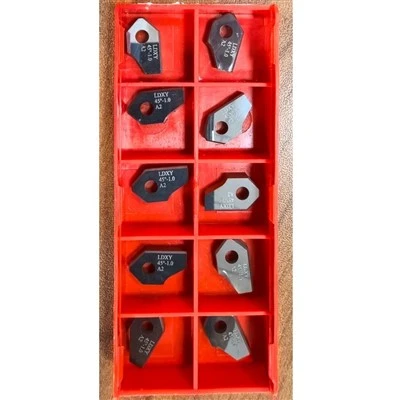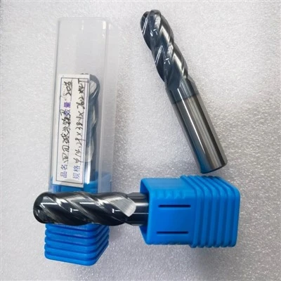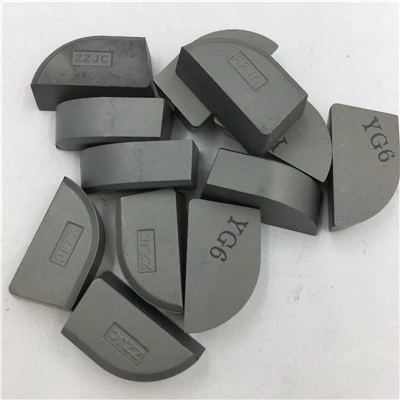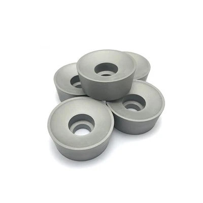


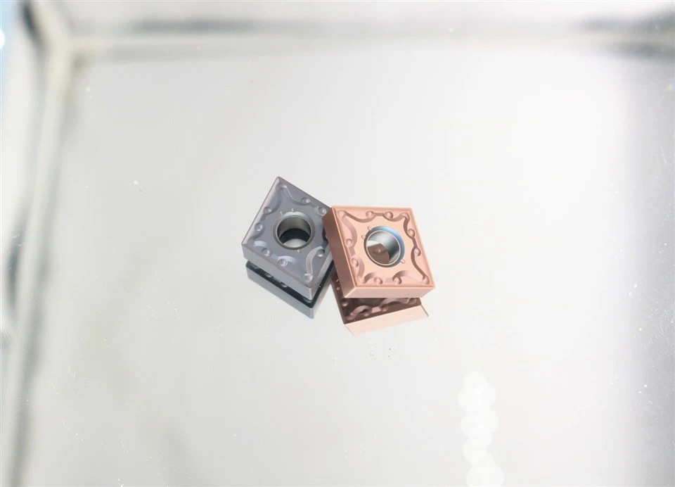
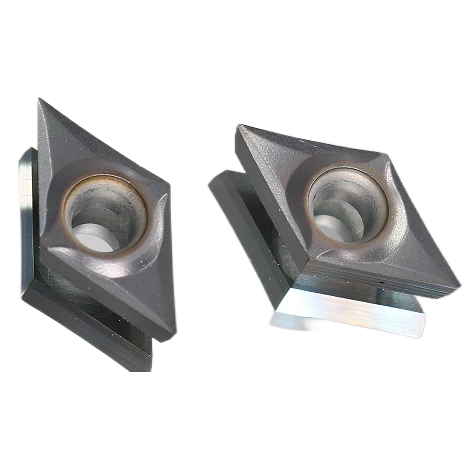
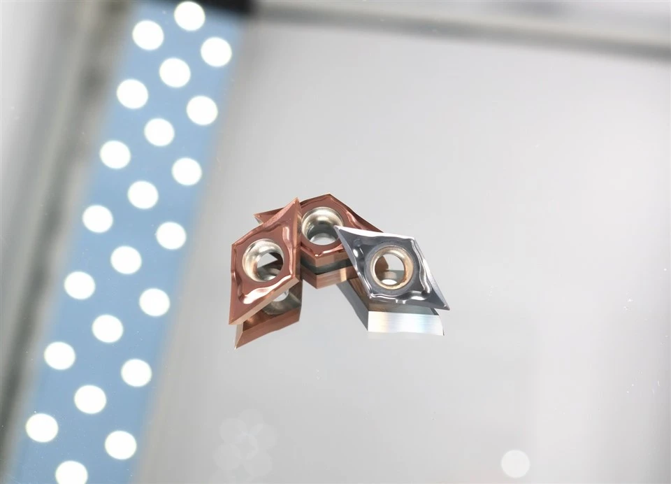
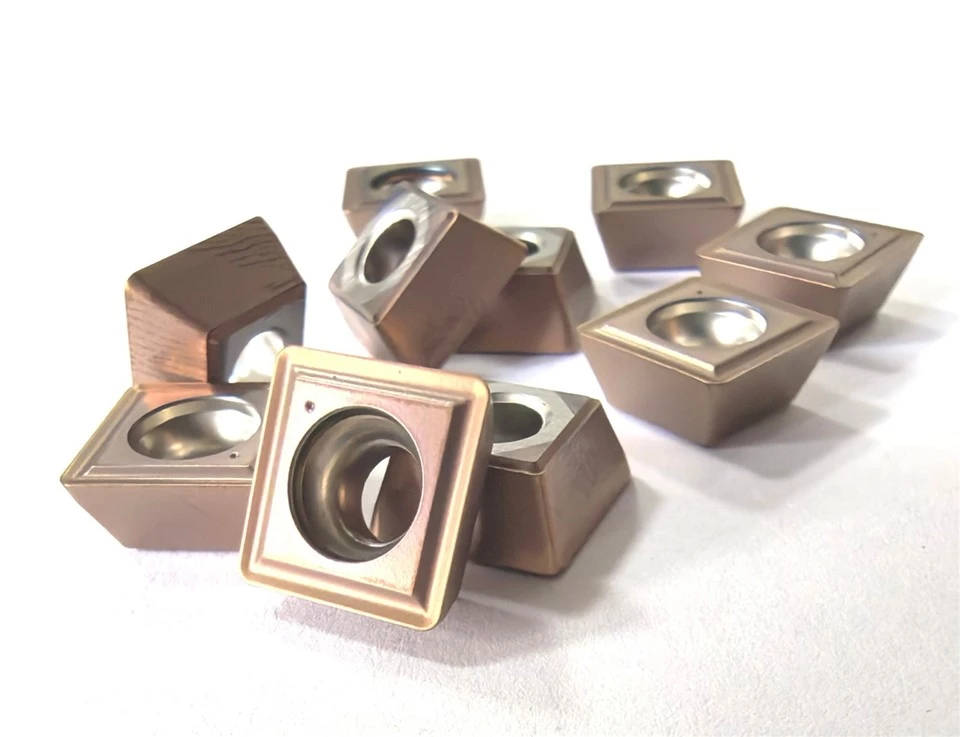
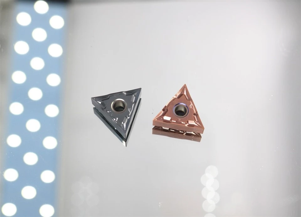
Carbide CNC inserts are the general term for interchangeable turning inserts, which are the mainstream tools in modern metal cutting processing and are widely used in turning, milling, cutting grooves, and thread processing, etc. According to their structure, they are divided into four categories: integral type, insert type (including welded type and collet type), shock-absorbing type, and special types. Among them, the collet type includes non-turning and turning types. In terms of material, they mainly use coated inserts, metal ceramic inserts, and hard alloy inserts, which have high wear resistance and high efficiency. The processing efficiency is more than four times higher than that of traditional welded inserts.

With the advancement of coating technology, the wear resistance and high-temperature resistance of CNC blades have been continuously improved, significantly enhancing processing efficiency and reducing production costs. The wear mechanisms include abrasive wear, adhesive wear, diffusion wear and chemical wear: the former two are caused by the scratching of hard particles and atomic-level adsorption of the material; the latter two involve the diffusion of high-temperature elements and chemical reactions of the cutting medium. High-speed steel cutting tools are prone to phase change wear due to the limitation of their phase transition temperature, resulting in a decrease in hardness. The model of CNC blades follows the ISO international standard, defining parameters such as blade shape, relief angle, chip-breaking groove type, etc. through 11-digit codes, and using precise formulas to calculate cutting speed and thread processing parameters.
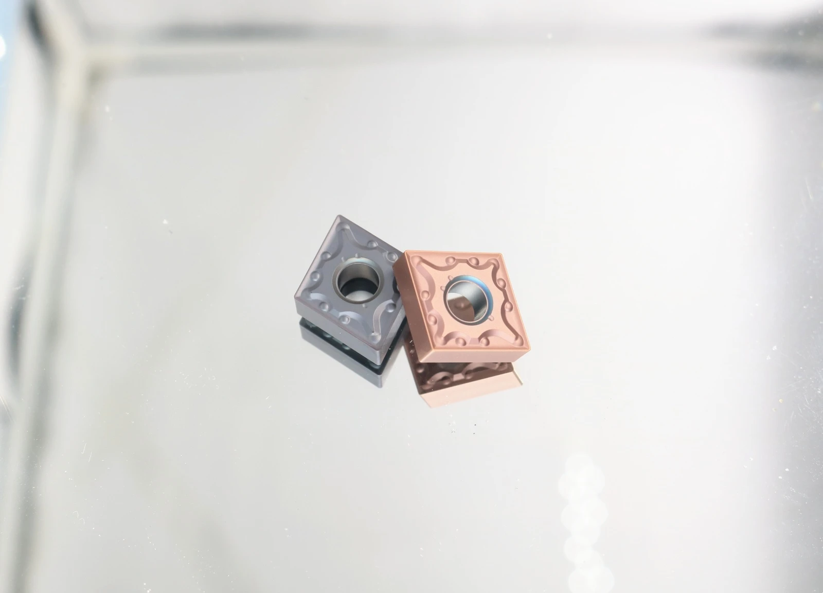
Classification
There are numerous types of CNC cutting inserts, which are widely used. They can be classified into the following categories:
CNC cutting inserts can be divided into various configurations based on their geometric shapes, such as square, circular, octagonal, rhombic, triangular, and curved shapes. They can also be classified according to the distribution of the cutting edge as single-edge or double-edge inserts.
Integral type: Made by grinding a single piece of material. During use, the cutting part can be ground into the desired shape according to different purposes.
Bonded type: It is divided into welded type and collet type. The collet type can be further classified into non-reversible and reversible types based on the different structures of the tool body. Modern collet-type reversible cutting inserts have diverse designs, such as the POMG double-sided pentagonal cutting insert with ten cutting edges; the Q6-MNMG is an inwardly concave equilateral hexagonal cutting insert; and the Q3-MCMT cutting insert adopts a positive angle structure.
Shock absorption type: When the ratio of the working arm length to the diameter of the cutting tool is greater than 4, in order to reduce the vibration of the tool and improve processing accuracy, a special structure of the tool is adopted. It is mainly used for boring.
Internal cooling type: The cutting coolant of the tool is transmitted to the internal part of the tool body through the main spindle or tool holder and sprayed onto the cutting edge through the spray holes.
Special types: Including strong clamping, reversible tapping, and composite tools, etc. CNC cutting tools mainly adopt collet-type reversible cutting inserts.
Material and Manufacturing Technology
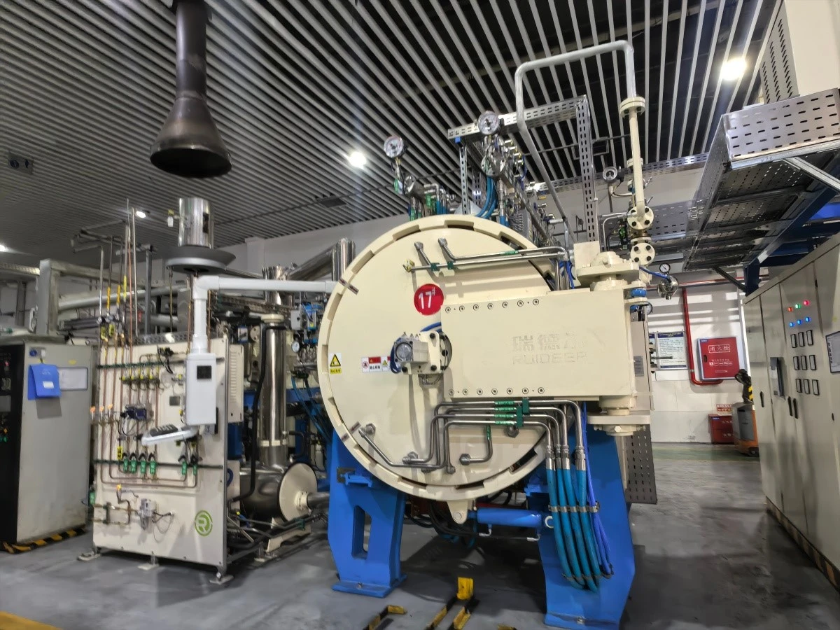
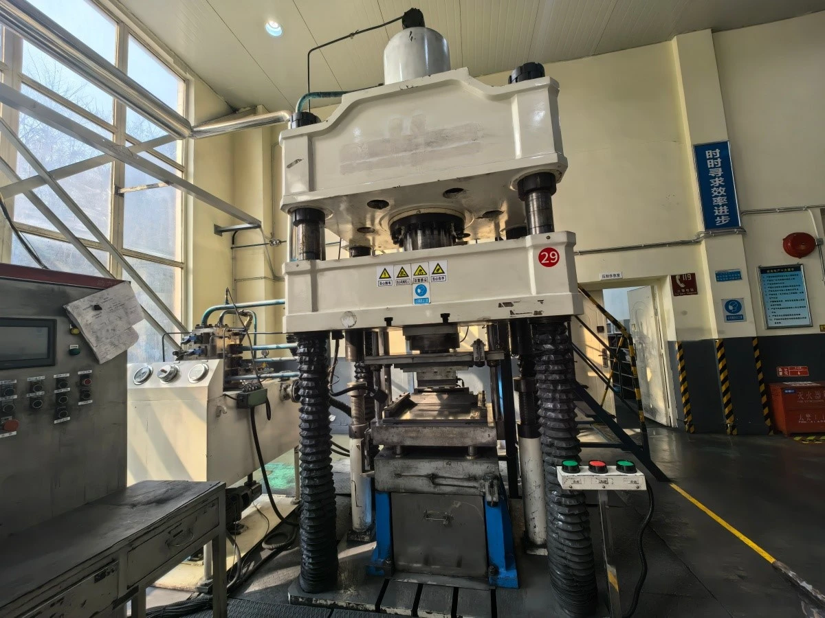
The hard alloy CNC blades are manufactured through powder metallurgy technology, using cobalt as the binder. They possess high hardness, wear resistance, and high-temperature resistance, and are suitable for processing various steels, cast irons, metals, etc. The manufacturing process typically involves powder preparation, pressing and forming, and high-temperature sintering at temperatures ranging from 1300 to 1700°C.
The ceramic blades are made of completely non-metallic materials, with higher hardness and greater brittleness, and possess better heat resistance and wear resistance, making them suitable for high-speed processing of most steels and cast irons. The manufacturing process is similar to that of hard alloys, including powder preparation, pressing and forming, sintering, and post-processing.
The ultra-hard materials mainly include cubic boron nitride and polycrystalline diamond. They are manufactured under ultra-high pressure and high-temperature conditions. Cubic boron nitride blades are typically used for processing very hard steels or cast irons, while polycrystalline diamond blades are used for processing non-ferrous metals, non-metallic materials, etc.
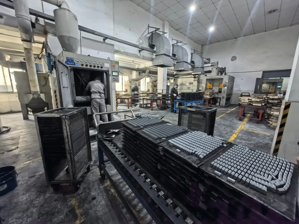
The sintered blades usually require post-processing procedures such as grinding, polishing, sandblasting, and coating.

Geometric shapes and design evolution
The interchangeable inserts have evolved from simple configurations to highly complex three-dimensional forms through innovative geometric topology, achieving cost control while regulating cutting mechanics to enhance processing efficiency and accuracy. In modern insert design, the traditional angular planar structure has been largely replaced by smooth three-dimensional surfaces, aiming to optimize the cutting geometry configuration to achieve a balance between chip control and chip breaking, expanding the processing adaptability range, and improving the utilization rate of the cutting material.
The concept of mechanically clamping hard alloy interchangeable inserts onto the tool body to form an assembled cutting tool was first applied in the late 1950s.
POMG is a double-sided pentagonal hard alloy insert, with its pentagonal structure and interchangeable design providing ten interchangeable cutting edges. The side shape design enables the insert to be clamped in a v-shaped tool groove, helping to improve rigidity. This insert design is used for two different cutting angles of tools: 55° for rough machining to semi-finishing, and 14.5° for high feed turning. The blade angle adopts a circular arc transition design and is equipped with a finishing plane, aiming to improve surface roughness.
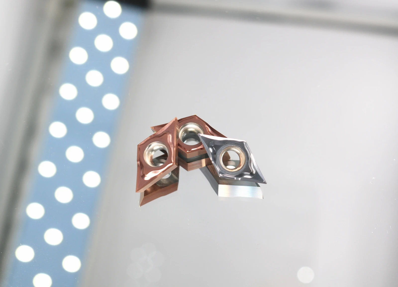
ISCAR's Q6-MNMG insert uses an inwardly concave equilateral hexagonal design, suitable for multi-directional turning, profiling processing, and end face turning operations, and is suitable for high-load rough machining. The insert has three locating ribs on both the front and back sides, which cooperate with the corresponding grooves at the bottom of the tool groove to ensure the stability of multi-directional turning.
The Q3-MCMT insert adopts a positive angle structure, with an inclined side and a bottom size smaller than the top. Compared to the negative angle contour of the double-sided insert, Q3's configuration provides a more positive rake angle for the cutting angle, which is more smooth and stable during the cutting process and provides better accessibility for processing hard-to-reach areas.
The tool body design also continues to innovate, such as ISCAR's CER-M-TURN series turning tools equipped with a tool body that can adapt to various replaceable tool holder modules, used for installing hard alloy, ceramic, cubic boron nitride, or polycrystalline diamond inserts. The tool body has a direction-adjustable high-pressure coolant outlet and an enhanced clamping mechanism to prevent brittle inserts from rotating or cracking.

Model Naming Rules
The model of a CNC blade is usually composed of 10 digits.
The first four letters represent the blade shape, the relief angle, the precision grade, and the front edge surface and center hole type. For example, D stands for a 55° rhombic blade, N stands for a 0° relief angle, M stands for the precision grade, and G stands for the front edge surface and center hole type.
The last six digits are divided into three groups, representing the cutting edge length, blade thickness, and tip arc radius in sequence. The letter at the end of the model indicates the blade material. For instance, P stands for general steel, M for stainless steel, K for cast iron, N for aluminum or non-ferrous metals, S for heat-resistant alloy or titanium alloy, and H for high-hardness materials.
This naming rule follows the ISO international standard.

Main causes of wear
The wear of the CNC tool blade is caused by abrasive wear, where some tiny hard particles (such as carbides, oxides, etc.) and impurities (such as sand grains, oxide scales, etc.) and adhered chip fragments, etc. are scratched onto the surface of the CNC tool blade, creating grooves, resulting in a mechanical wear. For high-speed steel tools with low cutting speed and low cutting temperature (such as reamers, taps, drills, etc.), this is the main cause of wear.
Bonding wear occurs when the normal pressure and cutting temperature between the rear cutting surface of the CNC tool blade and the workpiece surface, and between the front cutting surface of the CNC tool blade and the chip, cause fresh surface contact. When the contact surface reaches the atomic distance, adsorption bonding occurs. The bonding points gradually shear and tear the workpiece or chip away, causing bonding wear on the surface of the CNC tool blade. Bonding wear is one of the main reasons for the wear of hard alloys when cutting at medium to low cutting speeds.

Diffusion wear occurs under high temperature and high pressure, where certain chemical elements in the CNC tool blade material and the workpiece material mutually diffuse in the solid state, that is, elements such as Ti, W, Co in the hard alloy diffuse into steel, while elements such as Fe, C in the workpiece diffuse into the CNC tool blade, resulting in a decrease in hardness, strength, and increase in brittleness of the tool surface, and accelerated tool wear. This is diffusion wear, and it is one of the main reasons for the wear of hard alloy tools under high temperatures (800-900°C) during cutting.
Generally, the diffusion speed of W and Co is faster than that of Ti and Ta, so the high-temperature cutting performance of YT-type hard alloys is better than that of YG-type. Phase transformation wear occurs when cutting with high-speed steel tools, when the cutting temperature exceeds its phase transformation temperature (550-600°C), the microstructure of the CNC tool blade will change, resulting in a decrease in hardness, accelerated wear, and thus phase transformation wear is one of the main reasons for the wear of high-speed steel CNC tool blades. Chemical wear occurs at a certain temperature, where the medium around the cutting area, such as air and cutting fluid, undergoes a chemical reaction with the tool material, forming some loose and fragile compounds. These compounds are easily abraded and removed by the cutting and workpiece, causing wear on the CNC tool blade.

Tungsten Cemented Carbide Grade

Hot Products

Company Information
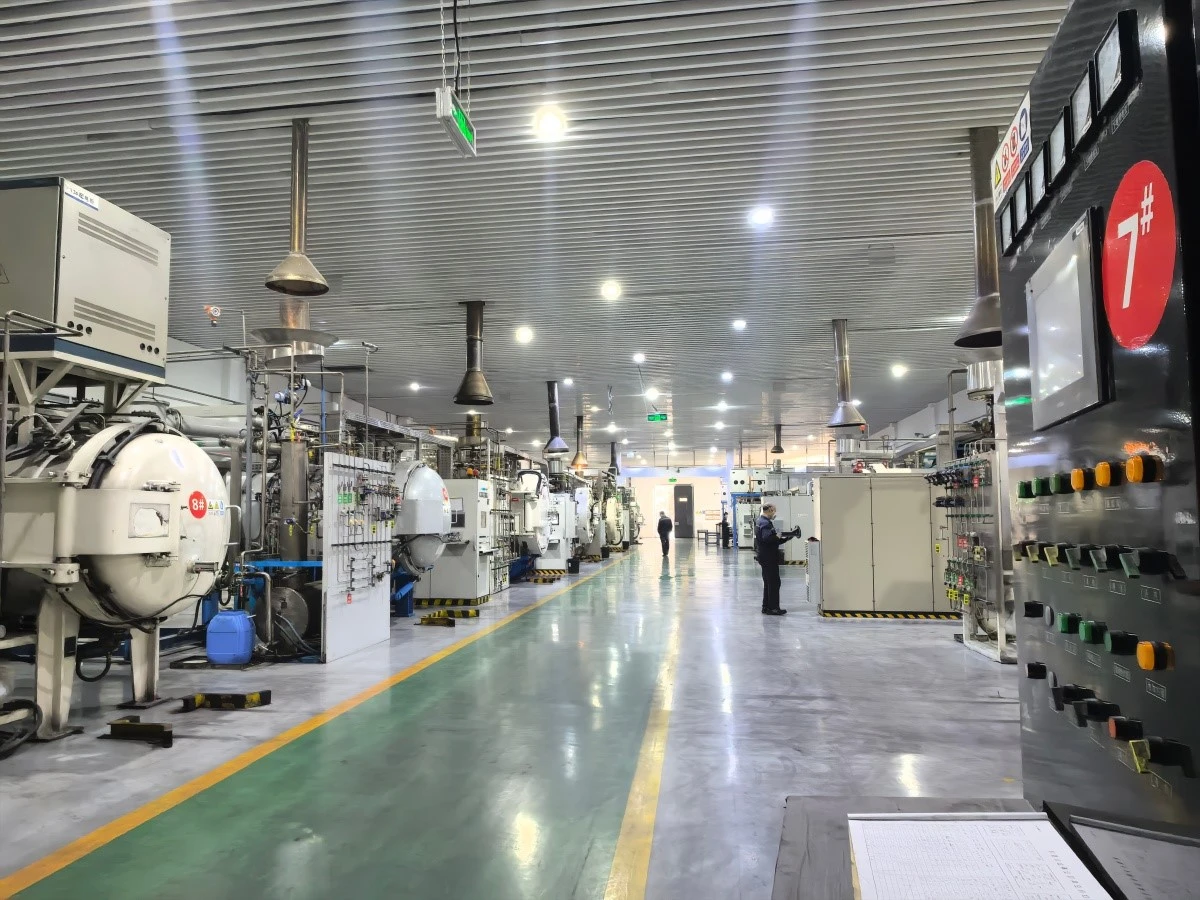
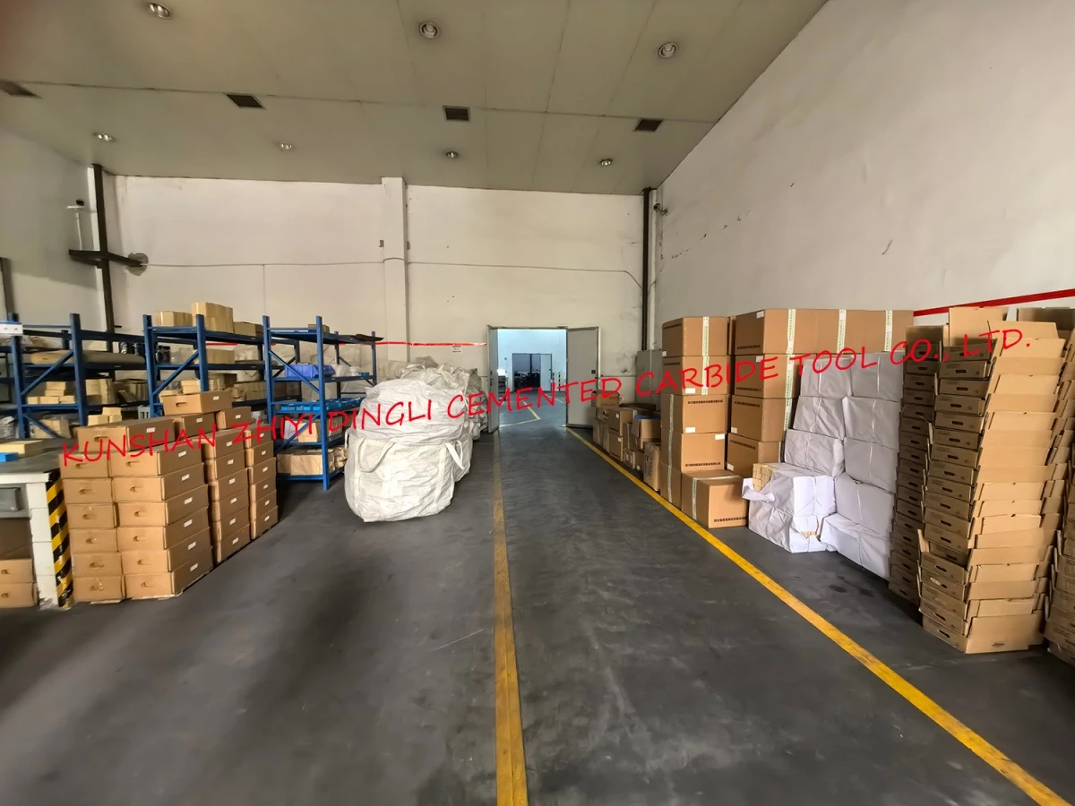
Kunshan Zhiyi Dingli Cemented Carbide Tool Co., Ltd. is a trusted manufacturer of carbide CNC inserts (interchangeable turning inserts) for modern metal cutting operations. Our inserts are widely used in turning, milling, grooving, and thread processing, and are produced in pressed, ground, and chip breaker types to meet diverse machining needs. Manufactured from premium tungsten carbide grades with precision edge preparation, our inserts deliver excellent cutting performance, long tool life, and consistent quality across a wide range of materials and applications.
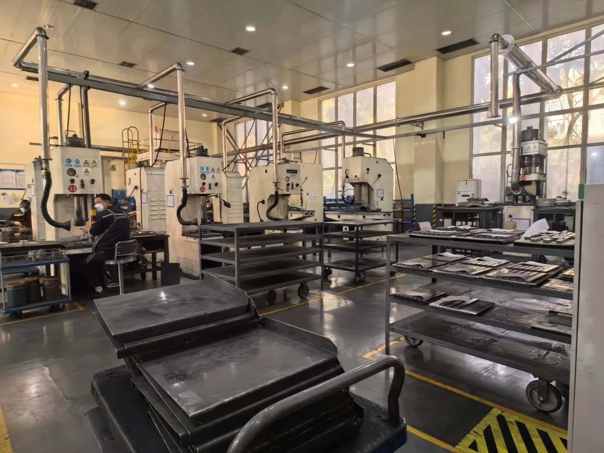
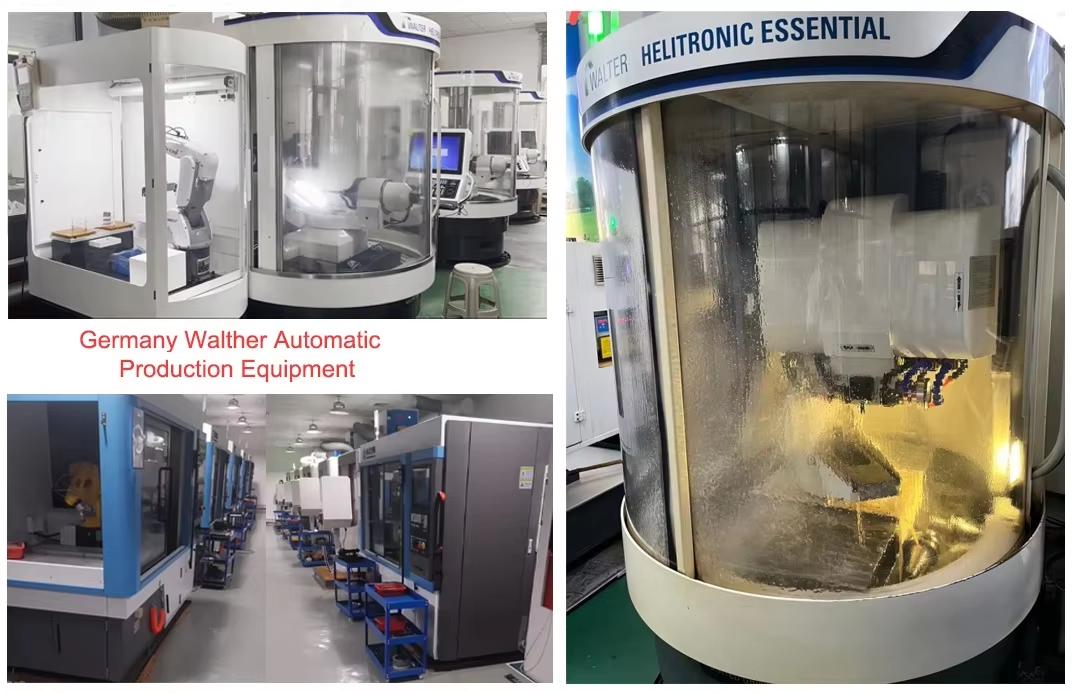
Our factory produces carbide CNC inserts in over 300 standard types including turning, milling, grooving, and threading inserts in pressed, ground, and chip breaker styles. With advanced powder pressing, sintering, and precision grinding capabilities, we achieve consistent edge quality and dimensional accuracy. Monthly production capacity exceeds 200,000 pieces, serving machine shops and tool distributors worldwide.




Testing Machine

Production Flow Chart

Packing & Delivery
Packing
1>Put the goods encased with plastic bag or plastic case in wooden box/carton/iron box, etc.
2>Other packing will be accept according to your needs.


FAQ
Q1: What types of CNC inserts do you produce?
A1: We produce turning, milling, grooving, and threading inserts in pressed, ground, and chip breaker styles.
Q2: What coating options are available?
A2: We offer uncoated and coated grades including TiN, TiAlN, and AlCrN coatings for different materials and applications.
Q3: What is the typical lead time?
A3: Standard types ship within 7-10 working days; special grades require 15-25 working days.
About Color Aberration
Product pictures are all physical photography, due to photo-taking technology, light, display parameters, etc., there may be differences between the received physical objects and photos, please refer to the physical.
Cargo Receipt
All our products go through strict inspection and count before shipment. Please check the goods in person when they receive them.
Please refuse to sign and contact us if you find that the CTN number and model is wrong or the product is damaged in transit.
Hot Tags: cnc carbide inserts, China cnc carbide inserts manufacturers, suppliers, factory